A Reducer is a mechanical device that lowers rotational speed and typically increases torque. It connects a motor to equipment that needs controlled motion, such as a conveyor belt, mixer, or lifting mechanism. The basic idea is simple. But a catalog ratio alone cannot tell you whether a unit will suit the job. Gear type, efficiency, heat, noise, and available installation space all matter. A small reducer mounted beside a warm motor may face different conditions from one running continuously in a clean, cool room.
Choosing the right reducer starts with the machine’s actual requirements. Confirm motor speed, required output speed, torque, operating hours, and the frequency of starts and stops. Note shock loads, mounting position, shaft arrangement, and nearby dust or moisture. Then compare suitable gear types, such as helical, planetary, or worm designs, using the manufacturer’s rated data. Check service factor, thermal capacity, lubrication needs, and allowable radial or axial loads—not just the headline torque. Measure the space, too. Installation details are easy to overlook. If the load or duty cycle is uncertain, ask a qualified supplier or engineer to review the calculations. A selection that looks right on paper may still need adjustment after real operating conditions are understood.
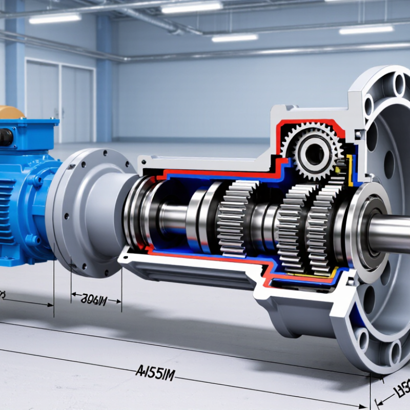
A reducer is a gear assembly that trades rotational speed for torque. Its ratio describes how much slower the output shaft turns than the input shaft. With a 10:1 reducer, the output turns once for every ten input turns. Ideally, torque rises tenfold; in practice, friction and heat reduce the delivered torque. At 90% efficiency, that example gives roughly nine times the input torque. Actual performance depends on load, lubrication, alignment, and temperature.
The ratio alone does not determine whether a reducer suits a machine. A conveyor may need steady starting torque, while a fast packaging line may prioritize output speed and compact size. The U.S. Department of Energy’s 2002 United States Industrial Electric Motor Systems Market Opportunities Assessment estimated that motor systems used about 63% of electricity consumed by U.S. manufacturing. The figure covers motor systems, not reducers alone, but it shows why drivetrain efficiency deserves attention. A mismatch can waste energy or strain connected equipment.
Tips: Check the required output speed and peak torque, not just the motor rating. Confirm service factor, mounting position, and duty cycle with the reducer’s technical data. Leave room for uncertainty: real loads may vary, and a calculated ratio is only a starting point.
A reducer changes motor motion into usable mechanical output. It usually lowers speed and increases torque through gears, belts, chains, or other transmission elements. For example, a small motor spinning at 1,800 revolutions per minute may drive a shaft at 180 revolutions per minute. The ten-to-one ratio trades speed for turning force.
Inside a geared reducer, a small input gear drives a larger gear. Each tooth transfers force across the contact point. Multi-stage designs repeat this process, while planetary systems share load across several gears. Worm mechanisms can provide high reduction in compact spaces, but they may create more heat. Belts and chains tolerate some misalignment, although they can slip or require tension adjustment. Motion is never transferred perfectly.
Choosing the right reducer starts with the output torque, speed, duty cycle, and available space. A dusty conveyor may need sealed housing and durable bearings. A positioning machine may need low backlash, since looseness can appear as visible error. Check service factors, efficiency, thermal limits, shaft direction, and mounting requirements. A quick ratio calculation helps, but it is not enough. Real loads often surge during startup or when material jams. I have seen a correctly sized unit run hot because ventilation was ignored. That mistake is easy to repeat. Measure the actual load when possible, then compare it with the reducer’s rated limits rather than relying on motor size alone.
A reducer lowers motor speed and increases usable torque at the output shaft. Its internal geometry affects efficiency, noise, heat, load capacity, and service life.
Worm reducers use a screw-like gear and a toothed wheel. They are compact, quiet, and often economical. However, sliding contact creates heat and reduces efficiency, especially at high ratios. Some designs resist back-driving, but this should never be assumed without testing.
Helical reducers use angled teeth that engage gradually. They usually run efficiently and quietly under continuous industrial loads.
Bevel reducers change the drive direction, commonly through a right-angle arrangement. They suit conveyors, mixers, and machines with limited installation space.
Planetary reducers share load across several gears around a central gear. This structure offers high torque density, stiffness, and accurate motion. It also demands careful alignment and may cost more.
Cycloidal reducers tolerate shock loads well and offer low backlash. Their eccentric mechanism may produce noticeable vibration if poorly aligned.
Choosing begins with measured data, not a catalog ratio alone. Record motor power, input speed, output torque, duty cycle, starts per hour, and ambient temperature. Check radial and axial loads at the output shaft. A washdown area needs different sealing than a dry workshop. For frequent reversing, verify backlash and peak torque separately. I have seen an oversized reducer fail because the coupling was misaligned. That mistake is easy to repeat. Service access, lubrication, mounting position, and spare-part availability matter too. A theoretical efficiency figure may not match a hot, dusty installation.
A reducer lowers speed and increases available torque between a motor and its driven load. Choosing one starts with the machine’s actual duty, not just the motor nameplate. Record required output speed, peak torque, starts per hour, and daily operating time. Include load inertia and shock; a conveyor carrying uneven bins behaves differently from a fan. Start with the load.
Compare the required ratio and reducer type with mounting space, shaft direction, and allowable backlash. Allow for service factor and thermal capacity, especially with frequent reversals or continuous heavy loads. Heat matters. Check lubrication, ambient temperature, dust, washdown exposure, and maintenance access at the installation point. A tidy calculation can still miss real operating conditions.
Efficiency deserves attention across the complete drive train. The U.S. Department of Energy’s 2014 sourcebook estimates that motor-driven systems use about 68% of U.S. manufacturing electricity. The report, Improving Motor and Drive System Performance: A Sourcebook for Industry, covers systems rather than reducers alone. Ask for efficiency data at the expected load, not only peak ratings. Where possible, verify the selection with actual load measurements; estimates can miss starts, jams, and operating temperatures.
A reducer lowers speed and increases available torque between a motor and driven equipment.
Choosing one by ratio alone can lead to a poor fit. Check the motor’s rated speed, required output speed, and starting torque. Then compare the reducer’s allowable torque with the machine’s real load, including frequent starts or sudden impacts. Leave a sensible margin, but avoid oversizing without reason; a larger unit may add cost and complicate installation.
Measure the available space and confirm the shaft diameters, keyways, and mounting position. Even a small mismatch can turn installation into a machining problem. Check whether the output shaft faces the right direction and whether the housing supports the expected loads. During installation, align the motor and reducer carefully, secure the base on a flat surface, and follow the specified fastener and lubrication instructions. Alignment matters.
Operating conditions deserve equal attention. Record ambient temperature, daily running hours, duty cycle, and exposure to dust or moisture. Compare these conditions with the reducer’s ratings, and check that the lubricant suits the operating temperature and mounting orientation. After startup, listen for unusual noise and watch for vibration, leaks, or rising temperatures. A brief test is useful, though it cannot replace checks under normal load. Document readings and revisit them after the equipment has run for a while.
A reducer lowers motor speed and increases usable torque at the output shaft. For example, 1,800 revolutions per minute may become 180. That is a ten-to-one reduction. Motion is never transferred perfectly.
A small input gear drives a larger gear through tooth contact. Each tooth transfers force across a moving contact point. Multi-stage units repeat this process. Planetary designs share loads across several gears.
Worm mechanisms provide high reduction in limited space. They often run quietly. However, sliding contact can create heat and lower efficiency. Do not assume they prevent back-driving without testing.
Helical reducers suit efficient, continuous operation. Bevel reducers change motion direction, often by 90 degrees. Planetary reducers provide high torque density and stiffness. Cycloidal reducers tolerate shock loads and can offer low backlash. Poor alignment may cause vibration.
Measure motor power, input speed, required output speed, and output torque. Record duty cycle, starts per hour, ambient temperature, and available space. Check radial and axial shaft loads. A catalog ratio alone is not enough.
Ventilation may be poor. Dust can block cooling surfaces. High ratios, continuous duty, or sliding contact may add heat. Compare real operating conditions with thermal limits. I have seen this mistake repeated.
Confirm shaft diameters, keyways, mounting position, and output direction. Secure the base on a flat surface. Align the motor and reducer carefully. Use suitable fasteners and specified lubrication. A small mismatch can become a machining problem.
Listen for unusual noise and watch for vibration, leaks, and rising temperature. Test briefly, then check the machine under normal load. Record readings after the equipment runs for a while. A short test can mislead. Recheck the assumptions.
A Reducer is a mechanical device that adjusts the relationship between a motor’s speed and torque. By reducing rotational speed, it can increase torque, helping equipment deliver the force and motion needed for a particular task. Reducers transmit motion through gears or other mechanisms, with different designs offering distinct advantages in efficiency, size, precision, noise, and load capacity.
Choosing the right Reducer starts with understanding the application’s required speed, torque, duty cycle, operating conditions, and available space. Compare suitable reducer types against these needs, while also considering efficiency, mounting arrangement, shaft configuration, and expected service life. Before selecting a unit, verify that its ratings and dimensions match the system, and confirm that installation, alignment, lubrication, and operating requirements can be met. Careful matching helps support reliable performance and avoid unnecessary wear or operating problems.
