A Motor Encoder is a sensing device that reports a motor’s position, speed, and direction. It converts mechanical movement into electrical signals for a controller. This feedback helps machines move accurately instead of relying only on applied voltage. In a robotic joint, for example, the encoder can detect whether a shaft has rotated 90 degrees or stopped slightly early.
Most encoders use optical, magnetic, or inductive sensing methods. An optical model may read light patterns from a rotating disk. A magnetic model can detect changes in a coded magnetic field. Incremental encoders usually produce pulses, while absolute encoders provide a unique position value. The controller interprets these signals and adjusts current through the motor driver.
The operating principle is practical.
When the shaft turns, the sensing element changes its output. The controller counts pulses or reads digital data. It then compares the measured position with the commanded position. Any difference becomes an error signal for closed-loop control. This process supports steady speed, precise positioning, and faster correction under changing loads.
However, encoder performance depends on installation and system design. Dust, vibration, electrical noise, and poor alignment can reduce accuracy. Resolution alone does not guarantee better motion. Mechanical backlash and delayed software responses may still affect results. A datasheet should be checked carefully, especially for signal type, voltage, mounting limits, and environmental ratings.
This article explains how a Motor Encoder works, how its signals reach a controller, and where common errors begin. The explanation uses simplified examples, so real systems may require deeper testing and calibration. Practical measurements remain essential.
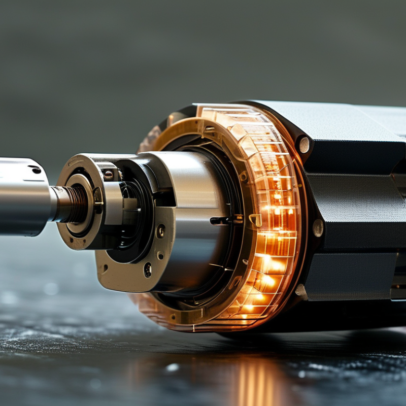
A motor encoder is a feedback device attached to a motor shaft or drive mechanism. It measures shaft position, rotation speed, and direction. The controller uses this information to adjust current and maintain the commanded motion. Optical encoders read light through patterned disks, while magnetic encoders detect changes in magnetic fields. Both methods convert mechanical movement into electrical signals.
An incremental encoder sends pulses as the shaft rotates. The controller counts these pulses and compares them with the target position. An absolute encoder provides a unique position value, even after power returns. This difference matters in robotics, conveyor systems, machine tools, and automated inspection equipment. Without feedback, a motor may keep turning after a jam or miss its intended position.
In practical commissioning, encoder alignment deserves careful attention. A technician may check the coupling, cable shielding, signal timing, and zero position. Small errors matter. One loose coupling can create false position readings and unstable movement. An encoder does not guarantee perfect accuracy by itself. Temperature, vibration, electrical noise, and mechanical backlash can still affect performance. Real systems need calibration and sensible control settings. I have found that a clean signal is often more valuable than a higher resolution number. More pulses can reveal more detail, but they can also expose installation problems.
What Is a Motor Encoder and How Does It Work?
Core Components Inside a Motor Encoder
A motor encoder converts shaft movement into electrical feedback. Its core components determine accuracy, speed, and reliability. The sensing element usually reads a rotating code disk or magnetic ring. Optical designs use an LED and photodetector. Magnetic designs use Hall-effect or magnetoresistive sensors. Each method has trade-offs.
The shaft connects the encoder to the motor. A precision bearing supports rotation, while the housing protects the sensing parts from dust, vibration, and heat. Inside, a signal-conditioning circuit strengthens weak sensor outputs. It then produces pulses or digital position data for the controller. Incremental encoders report movement steps. Absolute encoders retain a unique position value after power loss.
Small alignment errors matter. A slight gap change can distort the signal. Installation experience often reveals problems that datasheets do not explain clearly. The encoder interface may use differential signals to resist electrical noise over longer cables. According to the International Energy Agency’s Energy Efficiency 2023 report, motor-driven systems consume roughly half of global electricity. Reliable feedback therefore supports efficiency, stable speed, and safer control. A 2024 MarketsandMarkets analysis also identifies automation and industrial motion control as major drivers of encoder demand. These figures describe market and energy trends, not guaranteed performance. Temperature, bearing wear, and incorrect mounting can still reduce accuracy. A perfect specification cannot fix poor installation.
| Core Component or Feature | What It Does | Common Forms or Options | Key Technical Details |
|---|---|---|---|
| Encoder Shaft or Hub | Transfers the motor’s rotational movement to the sensing element. | Solid shaft, hollow shaft, through-bore, or shaftless mounting. | Must be aligned correctly with the motor shaft; excessive radial or axial load can reduce service life. |
| Code Disc or Magnetic Rotor | Creates the physical pattern that represents shaft position or rotational movement. | Optical glass or plastic code disc; magnetic ring or toothed magnetic target. | Optical designs use transparent and opaque tracks; magnetic designs are generally more tolerant of dust, oil, and vibration. |
| Sensing Element | Detects changes in light, magnetic field, or electrical coupling as the rotor turns. | Photodiode, Hall-effect sensor, magnetoresistive sensor, or capacitive sensor. | The sensor type determines environmental tolerance, signal quality, resolution, and maximum operating speed. |
| Signal-Processing Circuit | Converts raw sensor signals into clean digital pulses or position data. | Comparator, amplifier, interpolation circuit, microcontroller, or programmable logic. | May provide filtering, direction detection, index generation, error monitoring, and signal interpolation. |
| Bearing Assembly | Supports the rotating shaft and maintains the required mechanical position. | Sealed ball bearings or bearingless construction. | Bearingless encoders reduce rotating inertia and wear but require precise mechanical installation. |
| Housing and Protective Seal | Protects internal parts from mechanical damage, contamination, and moisture. | Metal or engineered polymer housing with gaskets and sealed cable exits. | Ingress protection ratings vary by design; the rating should be selected according to dust, water, and washdown exposure. |
| Power Supply | Provides electrical energy for the sensing and signal-conditioning circuits. | Common industrial supply levels include 5 V DC and 10–30 V DC, depending on the encoder design. | Correct voltage, current capacity, grounding, and cable shielding are necessary for reliable operation. |
| Output Interface | Sends position and speed information to a motor drive, controller, or motion system. | Incremental pulse output, analog sine/cosine output, or digital serial position data. | Interface selection depends on cable length, noise environment, controller compatibility, and required data rate. |
| A and B Quadrature Channels | Provide incremental position information and identify the direction of rotation. | Two square-wave channels shifted by approximately 90 electrical degrees. | Direction is determined from the phase relationship; counting rising and falling edges increases usable counts per revolution. |
| Index or Z Channel | Produces one reference pulse per revolution for homing or position verification. | Single pulse per revolution; some systems use a gated or position-qualified index. | The index does not normally provide absolute position by itself; a homing procedure is often required after startup. |
| Resolution | Describes how finely the encoder measures shaft rotation. | Incremental encoders are commonly specified in pulses per revolution; absolute encoders are often specified in bits. | For an absolute encoder, an n-bit position word represents up to 2n discrete positions per revolution. |
| Incremental Measurement | Reports relative movement through a stream of pulses as the shaft rotates. | A/B quadrature signals with an optional index channel. | Requires counting electronics and usually loses its position reference when power is removed. |
| Absolute Measurement | Reports a unique digital position value for each shaft angle. | Single-turn or multi-turn absolute position sensing. | Can retain position information during power loss, depending on the sensing and energy-storage design. |
| Speed Feedback | Allows the controller to calculate rotational speed and regulate motor performance. | Pulse-frequency measurement, period measurement, or decoded position change over time. | Higher pulse frequency and faster processing improve speed-feedback bandwidth, subject to encoder and controller limits. |
| Typical Applications | Provides feedback for closed-loop control, positioning, speed regulation, and motion synchronization. | Robotics, conveyor systems, machine tools, elevators, packaging equipment, and automated actuators. | The encoder must be matched to motor speed, resolution, mounting method, environmental conditions, and controller interface. |
A motor encoder is a sensing device that tracks a motor shaft’s movement. It converts rotation into electrical signals for a control system. Mounted near the shaft, it observes turning direction, angle, and speed. The controller reads these signals continuously. It can then adjust power when the shaft moves too far or too slowly. The signal is feedback. Without it, the system mostly guesses the motor’s position.
Incremental encoders detect movement through repeating pulses. The controller counts these pulses to estimate position and measures their timing to calculate speed. A shorter gap between pulses indicates faster rotation. Two signal channels usually help identify direction because their patterns are slightly offset. Some encoders provide an absolute position value instead. They assign a unique code to each shaft angle, even after power is removed. This method can be more informative, but it may require more complex electronics.
In practical equipment, encoder performance depends on alignment, wiring, and calibration. Dust, vibration, electrical noise, or a loose coupling can create false signals. A missed pulse may cause the controller to believe the shaft is elsewhere. That error can grow over time. Engineers often compare encoder readings with a mechanical reference during testing. This step is easy to underestimate. Even a well-designed system can need adjustment after installation, especially when temperature changes affect components or mounting surfaces.
A motor encoder converts shaft motion into electrical feedback for a controller. It reports position, speed, or direction. During commissioning, this feedback helps match commanded movement with actual movement. The main differences involve signal format, measurement method, resolution, and operating environment. No encoder is perfect.
Incremental encoders generate pulses as the motor turns. Two phase-shifted signals reveal direction, while pulse frequency indicates speed. They offer practical feedback and simple wiring, but they lose position information after power failure. An index pulse can provide one reference point per revolution.
Absolute encoders send a unique position value for each shaft angle. They retain position data without returning to a home point. Single-turn models measure one rotation, while multi-turn models track several rotations. This convenience usually requires more complex electronics. That matters.
Optical encoders use a coded disk and light sensor, allowing fine resolution and precise positioning. However, dust, vibration, or slight alignment errors can affect performance.
Magnetic encoders sense changing magnetic fields and generally tolerate dirty or damp machinery better. Their accuracy may decrease near strong magnetic interference.
Resolvers use electromagnetic coupling and suit harsh industrial environments, though their signal processing can be more demanding.
In real installations, the best choice depends on required accuracy, speed, temperature, shock, maintenance access, and controller compatibility. Small errors matter. A carefully protected incremental encoder may outperform a poorly installed absolute encoder.
What Is a Motor Encoder and How Does It Work?
Selecting the Right Encoder for a Motor Application
A motor encoder measures shaft position, speed, or direction and sends feedback to the control system. This feedback helps the motor move accurately under changing loads. Selecting the right encoder starts with the machine’s actual motion requirements, not only the motor’s rated power.
Choose an incremental encoder when the controller can establish position after startup. Select an absolute encoder when the system must know shaft position immediately after power returns. Resolution matters, but higher resolution is not always better. Excessive pulses can burden the controller and expose electrical noise. Check the required accuracy, maximum speed, response time, and available feedback inputs before choosing.
The installation environment deserves equal attention. Dust, vibration, moisture, heat, and limited mounting space can quickly damage a poor match. Confirm the shaft diameter, coupling method, housing protection, cable routing, and supply voltage. Signal type also matters. A long cable may require stronger noise resistance and proper shielding. Test the encoder with the real controller and motor whenever possible. Small timing differences can appear only during acceleration.
One practical warning: do not select by resolution alone.
A careful review also considers maintenance. Can technicians replace the encoder without disturbing alignment? Is calibration simple and repeatable? These questions are easy to overlook. I would also leave a small margin for speed and temperature, because laboratory conditions rarely match the factory floor. Testing may reveal that a cheaper, simpler encoder performs more reliably than a highly specified alternative.
A motor encoder is a feedback device attached to a motor shaft or drive mechanism. It measures position, speed, and rotation direction. The controller uses these signals to adjust motor current.
An encoder converts mechanical rotation into electrical signals. Optical types read patterned disks with light. Magnetic types detect changes in magnetic fields.
An incremental encoder sends pulses while the shaft rotates. The controller counts pulses to estimate position. An absolute encoder provides a unique position value after power returns.
Feedback shows whether the shaft follows its commanded movement. The controller can correct slow motion, overshoot, or position errors. Without feedback, the motor mostly guesses its position.
Pulse timing indicates speed. Shorter gaps usually mean faster rotation. Two offset signal channels can show the shaft’s direction.
Poor alignment can create false position readings and unstable movement. A loose coupling may shift the measured position. Small errors matter.
Dust, vibration, temperature changes, electrical noise, and mechanical backlash can reduce accuracy. A missed pulse may cause growing position errors. It needs checking.
Not always. More pulses reveal finer movement but may expose wiring or installation problems. A clean signal can matter more than a larger resolution number. That point deserves reflection.
A Motor Encoder is a sensing device that converts mechanical motion into electrical feedback, helping a control system determine a motor’s position, speed, and direction. It plays a vital role in motion control by allowing the system to compare actual movement with the intended command and make precise adjustments. Inside, an encoder typically includes a sensing element, a rotating code disk or magnetic target, signal-processing circuitry, and an output interface. As the motor shaft turns, the sensor detects changes in optical patterns, magnetic fields, or electrical signals and converts them into position or speed data.
Motor encoders are generally classified as incremental or absolute. Incremental types provide movement pulses and are useful for tracking speed and relative position, while absolute types provide a unique position value, even after power is restored. Choosing the right encoder depends on factors such as accuracy, resolution, operating environment, shaft configuration, response speed, communication method, and whether continuous position retention is required.
